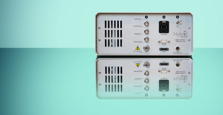
The MFAx1.3
Single Channel Mixed-Field Analyser (MFA)
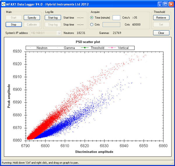
This extremely versatile digital analyser offers a complete real-time Pulse Shape Discrimination (PSD) solution for scintillation detectors with Multi-Channel Analyser (MCA) Pulse Height Spectra (PHS) analysis. The analyser has applications in coincident and multiplicity counting, security and safeguards, mixed-field assay and imaging.
The system can function with or without a host PC via an Ethernet connection. The PC connection affords the use of the PC-based Graphical User Interface (GUI) where system configuration, auto-calibration and the ability to analyse PSD and PHS data can be performed. When functioning independently (i.e. without a host PC) separate digital TTL outputs are available for analysis using secondary diagnostic instrumentation such as a coincident counter. The neutron and gamma TTL outputs toggle according to the event type, have a high real-time throughput, and are time correlated with the incident event.
An auto-calibration feature provides a convenient means for response matching detectors by automatically fine tuning the dedicated HV supply to align the PHS spectrum obtained using a calibration source (Cs-137).
Features at a glance
- 500 MSa/s sampling rate
- 12-bit resolution
- 3 Mpps PSD throughput
- Time correlated TTL outputs
- Built-in HV
- Fully user configurable
- Firmware upgradeable
- Windows(R)-based interface
- Low-contamination option
- EJ301, EJ309, EJ299 and CLYC compatibility tested.
Uses
- Neutron tomography
- Plutonium/uranium assay
- Multiplicity assay
- Mixed field imaging
- Spectroscopy